folded
Forums Newbie

Posts: 7
|
 |
« on: February 07, 2013, 04:31:02 AM » |
|
Hi, (This is my first post, so apologies if this is inadvertently off topic. Or boring) I thought I'd share a couple of things I've been playing with lately with the overall theme of generating meshes for 3d fractals. The endpoint of all this is to produce a mesh that is sufficiently simple that it can be 3d printed by shapeways, yet sufficiently detailed that it captures the interesting details of a fractal. I'm not there yet, but getting closer. If anyone has any thoughts or input, I'd really like to hear it. The simple stuff has been creating heightfield meshes on spheres for mobius and julia sets. To map the julia sets to a sphere, I've been using a stereographic projection to project from points on the unit sphere to the complex plane, then compensating for the stretching induced by the projection by iterating starting at c/|c|^2. The heightfield is based upon a blend between smoothed iteration and orbit trap. In the second image, vertices are coloured by the variance of the heightfield values with randomly sampled gaussian offsets (with sd = half the mean adjacent edge length). The idea behind this is that I can use the variance to recursively subdivide high detail regions, while keeping the tessellation of flat regions quite coarse.   Mobius fractals cover the sphere better, but don't really seem to lend themselves to interesting heightfield generation. I might just not have hit on the right mapping yet. Also, there are many more high frequency regions that I suspect it will not be possible to represent as a 3d object. 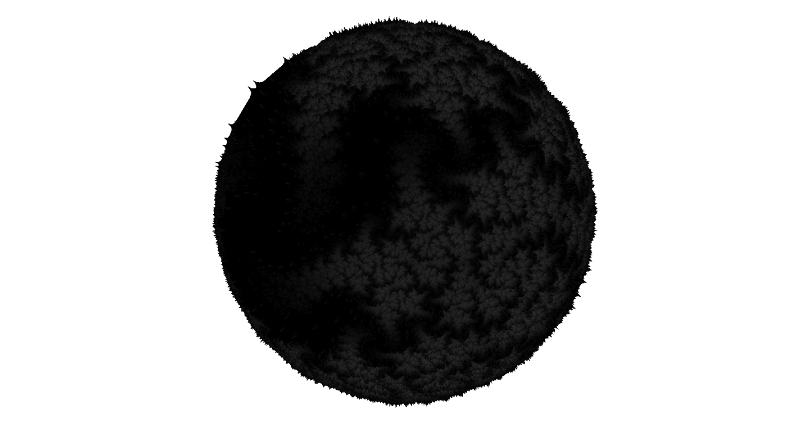 Finally, I've also been working with marching cubes isosurfacing of other 3d fractals, such as the following, inspired by http://www.fractalforums.com/3d-fractal-generation/4d-julia-3-sphere-intersection:  In this case my approach is to generate very high face count model segments recursively in an octree, and then simplify the partial results on the way back up to the root of the octree. Tests based upon simplifying a high face count mesh after generation finishes indicate that this is a feasible approach, but I need a good cost function to guide the selection of edges to collapse. I'm currently trying to build up enough courage to submit a mesh to shapeways to see what I get back... |
|
|
|
|
 Logged
|
|
|
|
|
Pauldelbrot
|
|
« Reply #1 on: February 07, 2013, 05:23:51 AM » |
|
For Julia sets on a sphere, you might want to try the Matchmaker fractal: }) For some choices of the parameters a and b, there are two finite attractors whose basins, together with the Julia set, comprise the whole Riemann sphere. The Julia set can range from fairly simple to quite convoluted. To convert from a unit sphere in 3-space to the complex plane, the upper half of the sphere is mapped to the unit disk by taking the ( x, y) coordinates of the point projected from the sphere onto the unit disk and then scaling by 1/(1 + sqrt(1 - r2)), where r = sqrt( x2 + y2). The lower half is mapped similarly, with the scale factor being 1/(1 - sqrt(1 - r2)), which notably sends r = 0 (the sphere's south pole) to the point at infinity. So, you'd want to triangulate the unit sphere at some resolution, then compute a height for each vertex by taking the vertex's x and y coordinates and which hemisphere it was on, applying the appropriate one of the above two transformations to get a point in the complex plane, and then iterating the above until many iterations or until a cycle detection method (Brent's, say) tripped with a tiny threshold. Then record the end point as the attractor, repeat the iteration until a disk about the attractor got hit while counting, and now you have an iteration count. You might want to use the relative positions of the logarithms of the disk radius about the attractor, the first orbit point to land inside that disk's distance to the attractor, and the disk radius times the distance of the second such orbit point divided by the distance of the first such, to compute a fractional iteration value to add to the iteration count to make a smoothed iteration value to use as the height, rather than just using the iteration count itself. Then, your vertex coordinates (including z) are multiplied by (1 + scale*height) and this is repeated for each vertex to generate your initial mesh, which you then simplify until it's suitable for 3D printing. |
|
|
|
|
Logged
|
|
|
|
|
|
folded
Forums Newbie
Posts: 7
|
|
« Reply #3 on: February 07, 2013, 02:46:36 PM » |
|
What tool do you use for marching cubes isosurfacing (from voxel slices) ? Fiji is the only one I know.
Both the heightfield and the marching cubes isosurface are my own code. It doesn't use calculated voxel slices, but instead uses the distance estimator to raymarch edges intersections at the isosurface boundary. At the moment the implementation is multithreaded CPU, but I'm considering a CUDA based version. At the moment I can wait a couple of minutes for the mesh to generate, but if I want to try multisampling the distance function then it might get to the point that I need the extra speed. I noticed another discussion on this today from late last year talking about Fiji and the stepping issues that caused simplification to produce poor results. I think the results I'm getting are pretty good. This is simplified down to about 2 million faces (1e6 vertices):  At present this simplification is done as a postprocessing step in meshlab, but I'm keen to do it inline with the mc mesh generation because a) It keeps the memory down. This mesh was simplified from an input of 67 million faces, which is just about the limit that my 16G machine can cope with, both in the mc code, and in meshlab. Working on small slices of the mesh at a time would make it practical to subdivide even further, and still end up with a mesh in the 1 million face range. b) Because you're doing it at the time at which you're evaluating the isosurface, rather than later, you have access to the function itself to guide the cost function used to simplify the mesh. My intuition is that that will be better than relying on the implicit encoding of that cost function by the mesh. I tried the variance based subdivision idea this evening, and the results weren't as good as I'd hoped. Fine ridges tend to disappear because they're not high enough area to appear in the samples used to calculate the variance. At the same time, it's still not enough to bring the face count down to a practical number. So again the solution may be to over-triangulate and then simplify. |
|
|
|
|
Logged
|
|
|
|
|
bib
|
|
« Reply #4 on: February 07, 2013, 03:21:42 PM » |
|
Thanks for the details (although I did not understand everything!). Well, if I understand correctly, the good quality of your mesh comes essentially from the very high number of faces in order to reduce stepping, and then the smoothing and decimation in Meshlab totally removes the stairs, or is it that your marching cubes algorithm is smart enough to produce faces with the right angles straight away (unlike Fiji that uses pure brute force)
|
|
|
|
|
Logged
|
Between order and disorder reigns a delicious moment. (Paul Valéry)
|
|
|
hobold
Fractal Bachius

Posts: 573
|
|
« Reply #5 on: February 07, 2013, 06:53:24 PM » |
|
or is it that your marching cubes algorithm is smart enough to produce faces with the right angles straight away (unlike Fiji that uses pure brute force)
This. His code has access to the underlying DE information, and therefor can make much better decisions where to put vertices than Fiji can after the fact. |
|
|
|
|
Logged
|
|
|
|
LMarkoya
Strange Attractor

Posts: 282
|
|
« Reply #6 on: February 07, 2013, 07:22:32 PM » |
|
Both the heightfield and the marching cubes isosurface are my own code. It doesn't use calculated voxel slices, but instead uses the distance estimator to raymarch edges intersections at the isosurface boundary. At the moment the implementation is multithreaded CPU, but I'm considering a CUDA based version. At the moment I can wait a couple of minutes for the mesh to generate, but if I want to try multisampling the distance function then it might get to the point that I need the extra speed.
I noticed another discussion on this today from late last year talking about Fiji and the stepping issues that caused simplification to produce poor results. I think the results I'm getting are pretty good. This is simplified down to about 2 million faces (1e6 vertices):
<Quoted Image Removed>
At present this simplification is done as a postprocessing step in meshlab, but I'm keen to do it inline with the mc mesh generation because
a) It keeps the memory down. This mesh was simplified from an input of 67 million faces, which is just about the limit that my 16G machine can cope with, both in the mc code, and in meshlab. Working on small slices of the mesh at a time would make it practical to subdivide even further, and still end up with a mesh in the 1 million face range.
b) Because you're doing it at the time at which you're evaluating the isosurface, rather than later, you have access to the function itself to guide the cost function used to simplify the mesh. My intuition is that that will be better than relying on the implicit encoding of that cost function by the mesh.
I tried the variance based subdivision idea this evening, and the results weren't as good as I'd hoped. Fine ridges tend to disappear because they're not high enough area to appear in the samples used to calculate the variance. At the same time, it's still not enough to bring the face count down to a practical number. So again the solution may be to over-triangulate and then simplify.
Your example is just beautiful Kudo's |
|
|
|
|
Logged
|
|
|
|
|
eiffie
Guest
|
|
« Reply #7 on: February 07, 2013, 08:08:13 PM » |
|
I was doing similar stuffs (code is here somewhere) a while back but gave up on the simplification step and just used meshlab. I think the method I would try is to simplify the slices as you go (limiting memory). You would have to leave some slices between then one you are generating and the one you are simplifying. Just a thought.
|
|
|
|
|
Logged
|
|
|
|
|
bib
|
|
« Reply #8 on: February 07, 2013, 10:27:59 PM » |
|
This. His code has access to the underlying DE information, and therefor can make much better decisions where to put vertices than Fiji can after the fact.
This is what I suspected, thanks. Even if I understand some concepts, unfortunately I'm not a programmer... So...Do you know what public 3D fractal software use that technique? Until 3D printers can accept voxel slices, this seems the right way to go. |
|
|
|
|
Logged
|
Between order and disorder reigns a delicious moment. (Paul Valéry)
|
|
|
folded
Forums Newbie
Posts: 7
|
|
« Reply #9 on: February 07, 2013, 11:58:39 PM » |
|
I spent a diverting morning on the train playing with Fragmentarium, and the formula suggested by Pauldelbrot. Here's the result:  (Larger version here: https://plus.google.com/u/0/photos/118387887168707366743/albums/5842333896614975201/5842333901324826514) The final fragmentarium script (attached) was a bit of a mongrel, taking bits and pieces from all over, but I'm pretty happy with the result. I iterated }) (a slight generalization) then coloured by min(abs(||z-pos||)-rad) The sphere is mapped to the plane using a stereographic projection. The good thing about this is that I also think that it can be used to make some interesting heightfields that don't have too many high frequency components and thus could be simplified well. For example:  Finally, I'm happy to make the source code to all of this available, if that would be interesting. It's not what you'd call user friendly, though. |
|
|
|
Logged
|
|
|
|
|
Pauldelbrot
|
|
« Reply #10 on: February 08, 2013, 06:43:23 AM » |
|
Cool! And thanks for translating Matchmaker to Fragmentarium. Maybe it will get more people finding beautiful Julia sets in it now.
|
|
|
|
|
Logged
|
|
|
|
folded
Forums Newbie
Posts: 7
|
|
« Reply #11 on: February 08, 2013, 07:07:06 AM » |
|
Cool! And thanks for translating Matchmaker to Fragmentarium. Maybe it will get more people finding beautiful Julia sets in it now.
I wouldn't claim that I've translated it as you described. I could probably have a better try at it. The orbit colouring isn't as you described, specifically. The shader makes the position of the orbit trap a parameter (which I just fiddle with until it looks ok). This bit might be hard to do in a shader - I don't think there's scope for computing constants in some initialization pass (but maybe I'm wrong). There's also the matter of how colours are calculated from disc hits that I didn't reproduce. If you had some code lying about for the matchmaker, then I'd be happy to produce a better version. |
|
|
|
|
Logged
|
|
|
|
|
Pauldelbrot
|
|
« Reply #12 on: February 08, 2013, 07:49:22 AM » |
|
The convergent smooth iteration method I suggested doesn't depend on precomputed constants in an earlier pass; just for each point X, - Copy X to P and Q. Set iter to 0, next to 1, max to 1,000,000 or whatever, and pcfct to 2.0 or 1.1 or something.
- Set tiny to 0.0000000001 or something and nano to 0.00000000000000001 or whatever.
- Iterate P. Compare P to Q; if within nano of each other, mark point as "periodic", otherwise increment iter and if iter exceeds max, mark point as "trapped". If iter exceeds next, multiply next by pcfct and copy P to Q. Repeat this list item until point marked as "trapped" or "periodic". (Matchmaker has no "escaping" points.)
- If point marked as "trapped" set height to max (or whatever) and move on to next point.
- Copy P to A. Copy X to P. Set iter to 0.
- Iterate P until within tiny of A, keeping count with iter.
- Set next to 0, copy P to Q, and iterate Q until it returns to within tiny of A, keeping count with next.
- Compute distance d from P to A and distance e from Q to A.
- Compute tiny2 = tiny*e/d.
- Compute [log(d) - log(tiny2)]/[log(tiny) - log(tiny2)] + iter/next and set as height.
That's the smoothed iteration value. (Note that if P, the first point inside tiny of A, lands near the outer edge of that disk, d will be close to tiny and the ratio added to iter will be near 1; the point barely landed in the disk so is nearly the next higher integer iteration. If P lands near tiny2, and given that tiny and tiny2 are related as d(P,A) and d(f(P),A) are related, then O defined by P = f(O) must be just outside the tiny disk since P is just outside the tiny2 disk, and in that circumstance the numerator of that ratio is near zero; the point almost needed one fewer integer iteration (O only just missed the tiny disk). So this ratio is a good fractional part to make a smoothed iteration. With Julia sets, precomputed global constants could be helpful (as you could find the attractors A in advance from critical points and avoid re-iterating points) but the above algorithm should work without them and works also for Mandelbrots (parameter-space images, so some of the attractors can move around, come, go, and otherwise change). |
|
|
|
|
Logged
|
|
|
|
|


