Logo by MarkJayBee - Contribute your own Logo!

END OF AN ERA, FRACTALFORUMS.COM IS CONTINUED ON FRACTALFORUMS.ORG

it was a great time but no longer maintainable by c.Kleinhuis contact him for any data retrieval,
thanks and see you perhaps in 10 years again

this forum will stay online for reference
News: Follow us on Twitter
 
*
Welcome, Guest. Please login or register. April 19, 2024, 11:13:42 PM


Login with username, password and session length


The All New FractalForums is now in Public Beta Testing! Visit FractalForums.org and check it out!


Pages: [1]   Go Down
  Print  
Share this topic on DiggShare this topic on FacebookShare this topic on GoogleShare this topic on RedditShare this topic on StumbleUponShare this topic on Twitter
Author Topic: Adaptive LOD  (Read 2730 times)
0 Members and 1 Guest are viewing this topic.
Snakehand
Guest
« on: December 16, 2009, 09:22:04 AM »

While refining my renderer a got a better understanding of some of the problems connected with rendering the mandelbulb, that is that the amount of detail varies greatly across the surface of the bulb. And often you will get a mix of well defined areas and overly smooth areas.

The reason for this can be seen when stepping up the iteration count one step at a time. Every step brings up the level of detail of a particular area one notch. This stepping effect can be particularly well observed when looking into the crevices.

But over a good nights sleep, I came up with a possible solution to this problem. In essence we do not wish to render details at a scale smaller than 1 pixel or so. In the 2D Mandelbrot, this problem takes care of itself. But on a 3D version an iterative approach can be taken.

In essence you start at say 4 iterations, the run a filter over the image which identifies smooth areas. In the smooth areas, you continue the ray marching for another iteration, and then run the filter again, (rinse and repeat). With this method it should be possible to avoid bitty regions.

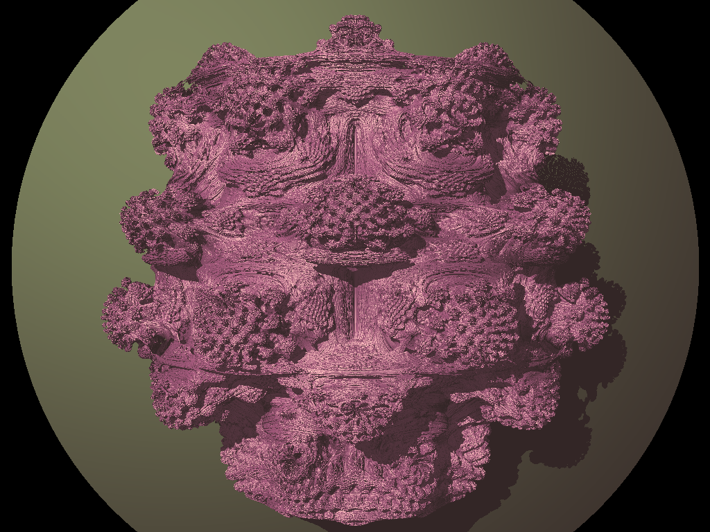
I am still refining the method, but have attached an early test render:

Logged
kram1032
Fractal Senior
******
Posts: 1863


« Reply #1 on: December 16, 2009, 04:17:47 PM »

Don't forget to take care of eventual antialiasing smiley Then you'll need to do the same for a certain amount of subpixels smiley
Logged
Snakehand
Guest
« Reply #2 on: December 16, 2009, 06:07:15 PM »

Don't forget to take care of eventual antialiasing smiley Then you'll need to do the same for a certain amount of subpixels smiley

You forgot to mention colour.  cheesy so far I am content with getting an accurate rendering of the surface boundaries. Here is another rendering:  Some artifacts of the method are still visible.


Edit:  Colour coded the different Levels Of Detail used for clarity.
« Last Edit: December 16, 2009, 09:45:33 PM by Snakehand » Logged
BradC
Safarist
******
Posts: 85


« Reply #3 on: December 16, 2009, 06:46:09 PM »

Cool idea, that's impressive.

I'm using a different technique for adaptive LOD that's not perfect but it seems to work pretty well. My raymarcher stops when the estimated distance to the fractal becomes smaller than a certain threshold, and this threshold dynamically depends on image resolution, camera field of view angle, and distance from the current point on the ray to the camera. I try to stop raymarching and render the surface when the estimated distance from the current point on the ray to the actual fractal becomes less than a pixel. Here's an example:

http://www.fractalforums.com/gallery/?sa=view;id=1192

With my method, sometimes certain areas still seem to be left too smooth and I'm guessing it's because my distance estimation is mis-estimating in those areas. I'm using a DE formula similar to the one David Makin posted on the main "true 3d" thread, but a little bit different. I haven't had a chance to try his formula yet; it might work better.
« Last Edit: December 16, 2009, 06:48:58 PM by BradC » Logged
Snakehand
Guest
« Reply #4 on: December 16, 2009, 10:02:02 PM »

I suppose I should also try the DE algorithm. I use a home grown "minimum" distance estimation to the bailout surface:

Code:
   
div = 100.0f+pow(3.5f,2.0f*here.x+here.y/128.0f+2.0f);
step = 1.0f/div;
prog = prog + step + 1e-6f;

here.x = bailout iteration count
here.y = escape distance squared after bailout (internal dot product of final Z)

I updated the image with colour coding, and it does appear very similar to other images coloured by iteration count, but having the surface determined by DE alone. It seems that DE may be the path to take.
Logged
Pages: [1]   Go Down
  Print  
 
Jump to:  


Powered by MySQL Powered by PHP Powered by SMF 1.1.21 | SMF © 2015, Simple Machines

Valid XHTML 1.0! Valid CSS! Dilber MC Theme by HarzeM
Page created in 0.158 seconds with 25 queries. (Pretty URLs adds 0.005s, 2q)