|
|
|
cKleinhuis
|
 |
« Reply #1 on: June 18, 2009, 02:06:31 AM » |
|
|
|
|
|
|
 Logged
|
---
divide and conquer - iterate and rule - chaos is No random!
|
|
|
|
Kimmo
Guest
|
|
« Reply #2 on: June 20, 2009, 06:10:38 PM » |
|
Cool, love to see higher res version...
|
|
|
|
|
Logged
|
|
|
|
|
David Makin
|
|
« Reply #3 on: June 21, 2009, 08:06:28 PM » |
|
|
|
|
|
|
Logged
|
|
|
|
|
Pauldelbrot
|
|
« Reply #4 on: June 22, 2009, 06:37:37 PM » |
|
Maybe post a sliced image, top half missing, to show the normal 2D M-set cross-section in context?
|
|
|
|
|
Logged
|
|
|
|
|
David Makin
|
|
« Reply #5 on: June 22, 2009, 06:41:53 PM » |
|
Maybe post a sliced image, top half missing, to show the normal 2D M-set cross-section in context?
Will sort something out... I wish I could get a few days off from "real" work to concentrate on 3D+ fractal rendering, I'm not progressing very fast on creating UF5 classes for general ray-tracing  |
|
|
|
|
Logged
|
|
|
|
|
David Makin
|
|
« Reply #6 on: June 22, 2009, 11:15:23 PM » |
|
|
|
|
|
|
Logged
|
|
|
|
|
David Makin
|
|
« Reply #7 on: June 23, 2009, 02:54:56 AM » |
|
One more, another cousin of the "True 3D" Mandy. This one is very complicated in detail, I have a hunch that it's truly fractal in all dimensions  The small image in the bottom-right is the "full" Mandy, the red box showing the location of the full-view (same location and parameters as the other recent renders I've done of the minibrot). 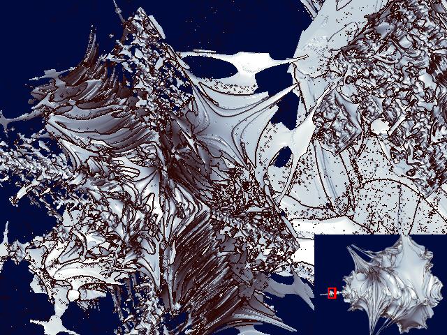 If the image above doesn't appear, go here: http://makinmagic.deviantart.com/art/quot-Real-3D-quot-Mandy-cousin-126890045Multiplication table for the unit vectors for this one: * | r i j k ---------------- r | r i j k i | i -r -k -j j | j -k -r -i k | k -j -i r |
|
|
|
|
Logged
|
|
|
|
|
lycium
|
|
« Reply #8 on: June 23, 2009, 07:11:36 AM » |
|
those speckles are why i use a probabilistic ("cloud") intersection algorithm: there is essentially no surface there (i.e. there is no fixed step size that will give coherent results).
also, when doing a close-up zoom like this you'll want to use a much smaller step size to eliminate the "layering" artefacts.
|
|
|
|
|
Logged
|
|
|
|
|
David Makin
|
|
« Reply #9 on: June 23, 2009, 12:59:04 PM » |
|
those speckles are why i use a probabilistic ("cloud") intersection algorithm: there is essentially no surface there (i.e. there is no fixed step size that will give coherent results).
also, when doing a close-up zoom like this you'll want to use a much smaller step size to eliminate the "layering" artefacts.
I'd be interested to see what your algorithm makes of this one I reduced the step-size by a factor of 10 on this one compared to the others, I didn't try reducing it further because even the render I did took 35mins at 640*480 ! (At the moment my step-size reduction algorithm isn't as "smart" as it should be - it reduces *all* step sizes when ideally it should only reduce them as the solid is approached, though actually for most of the errors I get with this algorithm I think that simply: for a given ray after calculating the next step size check that step size against the current minimum at that iteration depth, if it's larger than the current minimum for that iteration depth then step the current minimum instead, if it's smaller then update the current minimum). |
|
|
|
|
Logged
|
|
|
|
|
David Makin
|
|
« Reply #10 on: June 23, 2009, 01:46:12 PM » |
|
those speckles are why i use a probabilistic ("cloud") intersection algorithm: there is essentially no surface there (i.e. there is no fixed step size that will give coherent results).
also, when doing a close-up zoom like this you'll want to use a much smaller step size to eliminate the "layering" artefacts.
Just to add that in the solid on iteration density algorithm then there is always a definable surface, as there is using distance estimator, or indeed plain solid on iteration - in all cases the surface is not the ultimate limit of iteration (which is truly undefinable) but a finite approximation. The speckles and other errors appearing in the renders using my "solid on iteration density" algorithm are all down to errors in the calculation of the next step-size when ray-tracing. Essentially the algorithm is flawed in that because it's using solid on iteration density the step sizes should actually be based on the iteration density density rather than just the iteration density itself which is the case at the moment. |
|
|
|
|
Logged
|
|
|
|
|
cKleinhuis
|
|
« Reply #11 on: June 23, 2009, 02:16:21 PM » |
|
hi there, i just want to say .... would it be easier to perform ray intersection tests on an untransformed object ? i mean, wouldnt it be cooler to generate a true 3d model of the formula by just tracing horizontal/vertikal/straight depth lines to create a surface ? it could be done using a simple 3d value field, and then isocountouring the value field to extract a surface? i know this method would result in large arrays, and poor 3d model resolutions, but if a little bit tweaked ( render sub blocks extract geometry, render next block ) it could lead to good results ... i just mean, that the ray tracing attempt has similar disadvantages ( rough surface, even bigger errors when missing an "inside" volume element ) so that another method could lead to better results ... the resulting iso-surface could then be "global" illuminated as usual ...  |
|
|
|
|
Logged
|
---
divide and conquer - iterate and rule - chaos is No random!
|
|
|
|
David Makin
|
|
« Reply #12 on: June 23, 2009, 02:45:22 PM » |
|
hi there, i just want to say .... would it be easier to perform ray intersection tests on an untransformed object ? i mean, wouldnt it be cooler to generate a true 3d model of the formula by just tracing horizontal/vertikal/straight depth lines to create a surface ? it could be done using a simple 3d value field, and then isocountouring the value field to extract a surface? i know this method would result in large arrays, and poor 3d model resolutions, but if a little bit tweaked ( render sub blocks extract geometry, render next block ) it could lead to good results ... i just mean, that the ray tracing attempt has similar disadvantages ( rough surface, even bigger errors when missing an "inside" volume element ) so that another method could lead to better results ... the resulting iso-surface could then be "global" illuminated as usual ... You *can* do that - just use some of Terry Gintz software (e.g. QuaSZ) to render 3D fractals and then export them in the format you want for your preferred standard-3D rendering software such as Bryce or 3DSMax or Lightwave or Maya or whatever. The drawbacks are that for the sort of resolution I'm attempting in UF the export objects would get very large indeed and of course you have to use more than one piece of software to produce the final result (though I expect you could perform the entire process in Maya) |
|
|
|
|
Logged
|
|
|
|
|
David Makin
|
|
« Reply #13 on: June 24, 2009, 02:42:42 AM » |
|
On the subject of rendering and getting the surface - I sincerely hope this converts nicely to 3D from 2D. In the other thread on the "True 3D" Mandy I mentioned the possibility of solving: z = p + a*d and |In(z = z^2+c)|=@bailout for "a" where p is our viewpoint, a is the distance to step, d is the unit direction vector for the viewing ray and In(z^2+c) is the iterate of z^2+c to a given iteration depth n, well here it is in 2D - note that it's fairly sensitive to the various values used so I'm not sure how well it will perform for fractals other than plain z^2+c. Basically it's a directional distance estimator - note that I found I had to use cabs(In(z=z^2+c)) and the "correct" bailout value instead of the usual || and the squared bailout. Unfortunately this method also requires the derivative, so at the moment I only know how to apply it to Julibrots, Quaternions and standard Hypercomplex. Just copy and paste the whole thing into UF Try it using a specified direction vector. For comparison there's a (very slow) binary search alternative in the colouring formula. DirectionalDE {
::RkuwMhn2lJ1yOuNMMw7Gw/DC++mYLbZnsB6SR2er9S/AKYlpTYtskhk8mk/+K/opBo3EJHOz
QS15AVA0vnmwYBKoRZ2ZyhqAZNg+8HZsbUb4qsuKndFpLXDyqD5MN8AdeZxcbKH2SBfsR4Tq
l9NonMnq3zr2zzzPe6rxyoj6Z/QT/uHdDg5Uzee5cVeWayCVL6rgxZZlZfBU9Xc2JTbGzOCK
K8QWknzGwwVbrcYSHoRw7TTGgxRycZtd0EQn8t8di9RswFzs/6suIeYBxAcnmhEnlR0puiqe
ptrj1Ra0ADxZfIsbqbIjFpy9YO8tR6Oqzm7e8nkxTto0YTTWfuu2cgx3Fp1YNYaidK8/l0kB
B3LCdz663Np0Pl674tzkPAGF+hPQDQw62kdbsjICWTM+XApjqEvJxgJP+Z8cZdL2aG+WY+uq
6qKx+4+oq4YRZayFH0SR5Wsmfwaj31Hon5sBYZxXwITLeXmzUWdkii6mmGehYLd5W6ahQUek
PzyahoR2aosssgXy3yzFNbFqKbaeSzhDbZFFvQy/SXwPcUUdoJuLXP+vaYj9pJ/7XDuQkm8H
BRi44B==
}
work.ucl:NewDistanceEstimator {
::DZfSthn2dbVXrtNMU03L0/DXSHj4En2EPKs1mEKlO2b9lxebMQ1WuVMHpMJ5mGT/xvr+0xOp
MYlNYLQC++15Kd05KnSGnUdxxHdJAKNRqTBKvwaWKq5FwiotkmXLV0ZDd5huTc1BAr0k1Ebg
lVsVMN8236wbuFGfeAsWw4aEUHIwYTdJnlFjjI5ShL0ggDlSSumUFjv3ywleyhSwGxufaDTr
U0dyNsHtpuPGZ+m0rHIisSvV7zSquWy3lqy2hqelM14fXeKzTDdYh9Yx+bw/Ks0bKolMOFu5
jX/lPd8RYfqEEdsbqfI1Dv6OCrSUbgNGvmn3u+d+Up+g00dRJFyFrWXRfCKsA44/lei2vMxW
tjD/KNk7E1ypnOd67mldu9gaenaDo3003TewRTDifO+9k1snoVoif6pnPaoyI9TGFRycUyMZ
ti8ETTlB/S6aKRHs8whMzwmmkxtdpmrZVwzNNPvcRgygnfGGyWwmMLZ+0YfKB2yFTbBMw2RC
1t8GTTSppOSMwdHMdVabB9T3Jj6XaM/XEVUQ5xaPEbPd25Rnmq9UEDZEJHWyk9PrkZ8rVwA/
JUMZ/npYiH/I6TcnAnlTuTN09sFYkTuqWRfkmrFem3k+VOHu09GJe4dd2U4Kq+BRxiAl6Vj2
XHa2qdcTfhbC7fXJNIw2ntDvBqDzEug3IOWPmMy+aHOa08tMUlEdVwPrwkT2oGrZzZFE0MGj
4iFkluFlxpfXEJzm+2iuO6bn3BQfQrmPcAurMnIwWSe55HS7cTY70szoU769AzPGobHWNAY8
U08rHxCN70p221gxKgLt/eHNngCIAf9/Gh87quTlW9DCGePyHG19wPMiOeWyyF9n9NEPBxfY
3am4wTkk4Um4OwLictz4jMhISmPjO5cTHY9x2cJw8+tLo1I9GviPcCjXgnlxLLx33Tqr0XYi
pZ6Kz9oDuluBuhhyUeOFoKNbFBHbGYyZNRSWBu5lQPqXZK6a8ftK3CfmSk5PMwCiWwH4HFdt
Bzbmf5YBqFRPxsX2Zv3N9tfF9H2j1USi3Y9g7/rN4WhcFpqaLIJbVARSxzTlG0iNEZhC0PQB
hkdPjnagFtZoTBglI2AbF1wXbFQmPYM1aaOrcLe4WiK6C4RGdDjfP4WT4chSTJFnO4wL+Dvy
HOLdaS3C+JQOK6kz
}
|
|
|
|
|
Logged
|
|
|
|
|
twinbee
|
|
« Reply #14 on: June 24, 2009, 12:21:14 PM » |
|
Just to add that in the solid on iteration density algorithm then there is always a definable surface, as there is using distance estimator, or indeed plain solid on iteration - in all cases the surface is not the ultimate limit of iteration (which is truly undefinable) but a finite approximation. At the limit of iteration, also just to add that rendered in a high enough resolution (or with large enough over/down-sampling), it would appear like fog anyway. Perhaps zooming in far enough (even if it takes 10^(10^(10^10)) etc. zooms) would show a clearly visible surface as well. |
|
|
|
« Last Edit: June 24, 2009, 12:37:57 PM by twinbee »
|
Logged
|
|
|
|
|