Logo by stereoman - Contribute your own Logo!

END OF AN ERA, FRACTALFORUMS.COM IS CONTINUED ON FRACTALFORUMS.ORG

it was a great time but no longer maintainable by c.Kleinhuis contact him for any data retrieval,
thanks and see you perhaps in 10 years again

this forum will stay online for reference
News: Check out the originating "3d Mandelbulb" thread here
 
*
Welcome, Guest. Please login or register. April 18, 2024, 04:49:19 AM


Login with username, password and session length


The All New FractalForums is now in Public Beta Testing! Visit FractalForums.org and check it out!


Pages: [1]   Go Down
  Print  
Share this topic on DiggShare this topic on FacebookShare this topic on GoogleShare this topic on RedditShare this topic on StumbleUponShare this topic on Twitter
Author Topic: Mesh Julia 3D  (Read 2737 times)
Description: Another 3D fractal from Fractalworks
0 Members and 1 Guest are viewing this topic.
Duncan C
Fractal Fanatic
****
Posts: 348


WWW
« on: November 11, 2008, 02:05:20 AM »


(Click the image to see a much larger version with plot info)

I call this one "Mesh Julia." I like the texture and the repeating pattern of spikes.


Regards,

Duncan
Logged

Regards,

Duncan C
cKleinhuis
Administrator
Fractal Senior
*******
Posts: 7044


formerly known as 'Trifox'


WWW
« Reply #1 on: November 11, 2008, 10:53:14 AM »

this is an amazing resolution, respects cheesy and very smooth ...
you did not include the mesh resolution for that plot ?
i belive it is above 2000x2000 ?

can you erode the julia set in the middle a little bit ? cheesy :smiley
Logged

---

divide and conquer - iterate and rule - chaos is No random!
Duncan C
Fractal Fanatic
****
Posts: 348


WWW
« Reply #2 on: November 12, 2008, 12:35:50 AM »

this is an amazing resolution, respects cheesy and very smooth ...
you did not include the mesh resolution for that plot ?
i belive it is above 2000x2000 ?
Trifox,

This image is actually the left eye view of a stereogram I created for "printing" to a pair of 35 m slides. That 3D image was written at 4096x2732 pixels. The source 2D image was 3000x3000 pixels.

That image size is overkill for screen display. For the best smoothness, I usually render my 3D images at 2X the target resolution, then down-sample and sharpen. So if my target is 800x800, I'll create an image at 1600x1600 and downsample it.

can you erode the julia set in the middle a little bit ? cheesy :smiley
Not with my current program. Right now I set the height of all the pixels the same. I'd need some way to describe the area I wanted to "erode." Any suggestions as to how to describe the region where I would reduce the height?


Duncan C

Logged

Regards,

Duncan C
cKleinhuis
Administrator
Fractal Senior
*******
Posts: 7044


formerly known as 'Trifox'


WWW
« Reply #3 on: November 12, 2008, 12:46:44 AM »

use a an additional distance estimator cheesy

and simply use it as additional height ( not neccessarily color ) information/addant/scale factor

the distance estimator would give a nice approximation of the fractal shape, i think it would be best to use the distance estimator to
approximately 5-10 iterations less than current max value, and then simply add it to the 3d height...l
 afro
Logged

---

divide and conquer - iterate and rule - chaos is No random!
Duncan C
Fractal Fanatic
****
Posts: 348


WWW
« Reply #4 on: November 12, 2008, 03:46:54 AM »

use a an additional distance estimator cheesy

and simply use it as additional height ( not neccessarily color ) information/addant/scale factor

the distance estimator would give a nice approximation of the fractal shape, i think it would be best to use the distance estimator to
approximately 5-10 iterations less than current max value, and then simply add it to the 3d height...l
 afro

Trifox,

My app already has a "height factor", which is a simple multiplier for the height values of all my points, and a "steepness" adjustment, that raises all the height values (which are in the range) to a power between 0.01 and 2.0.

Steepness values less than 1 expand changes in plot height at the low range and flatten out points near the top of the range. (Make the valleys bumpier and the peaks smoother)

Steepness values greater than one expand changes in plot height near the top of the range and flatten out points at the low range (make the peaks steeper and the valleys smoother)

If I could figure out what part of the plot to adjust, I could adjust those two factors. To "erode the center" I could lower the height factor value or the peak steepness value in the area I want to "erode". The question is, how do I define the region I want to adjust, and how do I phase in the changes so the change isn't sudden and bad looking.


Duncan C
Logged

Regards,

Duncan C
cKleinhuis
Administrator
Fractal Senior
*******
Posts: 7044


formerly known as 'Trifox'


WWW
« Reply #5 on: November 12, 2008, 11:01:25 AM »

i think that you only have the iteration depth as help factor,

i think of a way to interpolate the two values you describe from a certain iteration range to the end

so, the julia shape you want to erode is the near the max iteration, or ?
Logged

---

divide and conquer - iterate and rule - chaos is No random!
Duncan C
Fractal Fanatic
****
Posts: 348


WWW
« Reply #6 on: November 12, 2008, 08:00:19 PM »

i think that you only have the iteration depth as help factor,

i think of a way to interpolate the two values you describe from a certain iteration range to the end

so, the julia shape you want to erode is the near the max iteration, or ?


My 3D plots usually use the distance estimate value to calculate height.

The "Mesh Julia" plot has heights inverted (the taller a point, the further it is from a Julia set point.)

Using distance estimates to decide where to "erode" (flatten) the plot wouldn't work, because distance estimate values vary all over the plot. Iteration values might work.

I was thinking in terms of defining a circular area of the plot. Anything inside the circle would be flattened, and anything outside would be left alone. There would be a transition area near the boundary.
Logged

Regards,

Duncan C
cKleinhuis
Administrator
Fractal Senior
*******
Posts: 7044


formerly known as 'Trifox'


WWW
« Reply #7 on: November 12, 2008, 11:03:04 PM »


I was thinking in terms of defining a circular area of the plot. Anything inside the circle would be flattened, and anything outside would be left alone. There would be a transition area near the boundary.

yes, that was also my first thought, and it might be discussed elsewhere before, but the main problem with that
is that it would destroy the fractal shape, and it must be carefully adjusted, and one simple shape would never be enought sad ... too much work !

but, think about reducing the iteration for the height adjustment, the problem is the increasing frequency of height changes at higher iteration depth, and this could be overcome with the smooth alignment of the distance estimator, the distance estimator also gets rubbish at higher dimensions, or increasing frequency in height changes ... but .. if you would stop the distance estimator at ~-10% of max iteration, i think it would be an improvement in 3d image quality

but i havent tested it ...just a thought  afro
Logged

---

divide and conquer - iterate and rule - chaos is No random!
Duncan C
Fractal Fanatic
****
Posts: 348


WWW
« Reply #8 on: November 13, 2008, 03:25:35 PM »


I was thinking in terms of defining a circular area of the plot. Anything inside the circle would be flattened, and anything outside would be left alone. There would be a transition area near the boundary.

yes, that was also my first thought, and it might be discussed elsewhere before, but the main problem with that
is that it would destroy the fractal shape, and it must be carefully adjusted, and one simple shape would never be enought sad ... too much work !

but, think about reducing the iteration for the height adjustment, the problem is the increasing frequency of height changes at higher iteration depth, and this could be overcome with the smooth alignment of the distance estimator, the distance estimator also gets rubbish at higher dimensions, or increasing frequency in height changes ... but .. if you would stop the distance estimator at ~-10% of max iteration, i think it would be an improvement in 3d image quality

but i havent tested it ...just a thought  afro

Trifox,

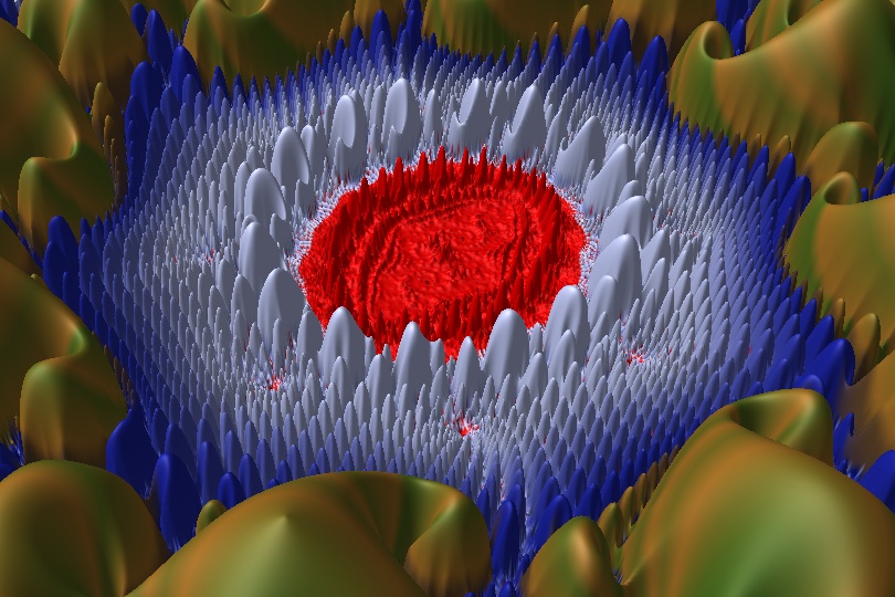
I think you may be on to something. As a test I replotted the fractal with the color forced to bright red for the 7% of pixels with the highest iteration counts, and the boundary is just about right for an area to "erode" (or flatten.)

My app already uses distribution of pixels by iteration count to do coloring, so this was very easy to do.  Here is the resulting image:


I could add an option to my program to flatten the height of pixels that are in the highest iteration bands. I would need a way to feather the boundary so there wasn't a sudden drop in pixel heights.

I also find that with Mandelbrot and Julia set images, using distance estimates to color the thin filaments surrounding Mandelbrot/Julia set points frequently ruins the fine detail in areas of the plot with the most Mandelbrot/Julia set points. The settings that give nice fine outlines for the rest of the plot turn the center of some plots to mush.

(This is hard to describe. I may post a sample image to show what I mean.)
It may be that I can use a similar iteration count based approach to thin out the outlines around those parts of a plot. Thanks for the suggestions.


Regards,

Duncan C
Logged

Regards,

Duncan C
Duncan C
Fractal Fanatic
****
Posts: 348


WWW
« Reply #9 on: November 14, 2008, 05:05:28 AM »

In my previous post I mentioned that using the Distance Estimate Method (DEM) to color the thin "tendrils" surrounding a Mandelbrot or Julia set plot didn't work that well for areas that are near large collections of Mandelbrot or Julia set points. Here are a couple of plots that show what I'm talking about. First, a Julia set plot that does not use DEM. It has a color gradient from red to black at the highest iteration values, and shows nice, subtle detail of the shape in the center of the plot:


The second image shows the same plot, but with pixels with a low DE value forced to black. Note that the fine details on most of the plot are quite good. If anything, they are a bit too thin.


However, the area in the middle of the plot is a mess. It's a big black blob with no detail left.

If I used my iteration value to "attenuate" the DEM based coloring, it might well fix that problem. For pixels with a high iteration count, I would not change their color unless their distance estimate value was much higher.


Duncan C
Logged

Regards,

Duncan C
Pages: [1]   Go Down
  Print  
 
Jump to:  

Related Topics
Subject Started by Replies Views Last post
Mandelbulb 3D : How to export 3d mesh ? Tutorials « 1 2 » alainlioret 21 41761 Last post March 21, 2015, 02:06:03 PM
by Sockratease
Mesh 3d Art / Composition trafassel 0 2109 Last post April 27, 2011, 11:15:41 PM
by trafassel
Koch Mesh Fine Mandelbulb3D Gallery mario837 1 1021 Last post May 15, 2011, 05:58:14 PM
by DarkBeam
Nano Mesh Mandelbulb3D Gallery Tahyon 2 1349 Last post December 19, 2013, 09:31:32 PM
by alij
example mesh + mesh lab Mandelbulb3D Gallery ericr 1 2153 Last post March 14, 2016, 05:16:06 PM
by ericr

Powered by MySQL Powered by PHP Powered by SMF 1.1.21 | SMF © 2015, Simple Machines

Valid XHTML 1.0! Valid CSS! Dilber MC Theme by HarzeM
Page created in 0.182 seconds with 24 queries. (Pretty URLs adds 0.008s, 2q)